¡¾4PPoE¡¿TSB-184-A: Guidelines for Supporting Power Delivery
TSB-184-A£º
Balanced twisted-pair copper cable is not just for data communications anymore. The number of devices capable of being powered through their network connection is growing. Trends like the Internet of Things (IoT) and internet protocol (IP)-enabled devices are driving up the number of connections to the network. The growing deployments of wireless access points (WAPs) needed to support increasing data consumption are making the ability to have power and data over the same cable very appealing.
New standards are defining the supply of up to 100watts (W) of power with 1000milliamps (mA) of current per pair. Power can cause heat, and heat can cause reduced data transmission performance in a balanced twisted-pair copper cable. Cable life is usually expected to be at least 10 years on average. Therefore, it is important to understand the impact on performance and installation considerations for twisted-pair cabling today because the same cable might also deliver power in the future. TSB-184 provides guidelines for supporting power delivery over twisted-pair cabling simultaneously with data.
What Is TSB-184?
TSB-184 is a technical service bulletin that provides guidelines for twisted-pair cabling to support the remote delivery of power in parallel with data transmission. There are many factors that can impact the ability of a cable to support both data and power, including how the cable is installed, whether the cable is bundled or unbundled, the type of pathway, and the gauge of the cable. The purpose of the guidelines is to help limit and manage temperature rise of the cable so it does not increase by more than 15 degrees Celsius (¡ãC [27 degrees Fahrenheit (¡ãF)]). Managing the temperature rise of the cable can reduce long-term cable degradation. The negative effect of higher temperatures on transmission performance will also be minimized and the amount of heat added to the surrounding environment will be reduced.
TSB-184 was originally published by the Telecommunications Industry Association (TIA) in 2009. This is the same year that IEEE published the 802.3at standard for Type 2 power over Ethernet, commonly referred to as PoE+. This standard doubled the power delivered by the sourcing device to 30W and almost doubled the current per pair to 600 mA over the original PoE standard (Type 1).
IEEE has been working on a new PoE standard (IEEE802.3bt) for Type 3 and Type 4 PoE (PoE++ <4PPoE>), elevating the potential power delivered by the sourcing device to 100 W, with about 1 ampere (A) per pair. (Note: 1 A is equal to 1000 mA). This standard is expected to be completed in early 2018. In response to this standard, TIA updated TSB-184 and published the A revision (TIA TSB-184-A) in March 2017.
THE NEED FOR TSB-184
The need to develop TSB-184 was motivated by applications like the IEEE Standard 802.3 Data Terminal Equipment (DTE) Power to support LAN devices with remote power. There have been apparatuses in the market for a while that can be supported by remote powering, such as WAPs, along with building automation and security devices like remote cameras, IP telephones, biometric access controls and multimedia devices.
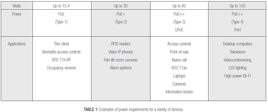
As the number and types of apparatus have increased, so has the required power to operate them. Devices like thin clients, 802.11n WAPs and sensors typically require up to 15 W to operate. However, radio-frequency identification (RFID) readers, video IP phones and pantilt-zoom IP cameras may require up to 30W. The support of point-of sale devices, laptops, larger cameras and information kiosks can require as much as 60W; and TVs, desktop computers, video conferencing and LED lighting can require as much as 100 W of power to operate. These latter devices are the type driving the new IEEE standard for Type 3 and Type 4 PoE. Table 1 provides examples of power requirements for different devices.
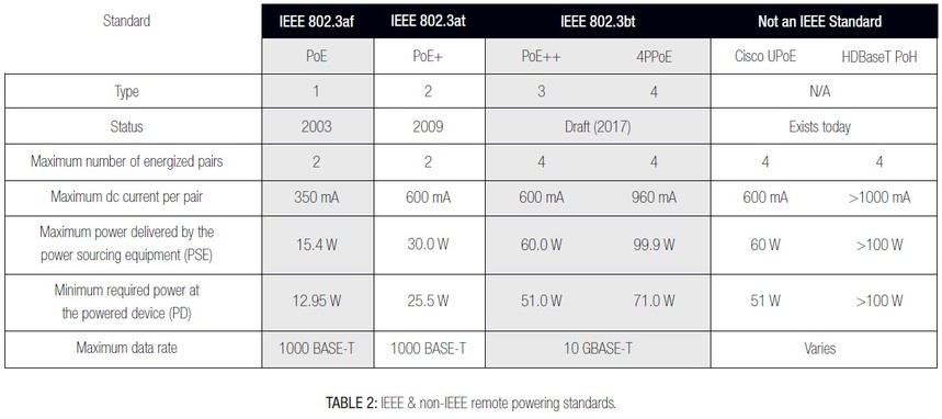
Table 2 summarizes the IEEE PoE standards that have been published or are in development. There are two other remote powering options listed that are not IEEE standards: Power over HDBaseT (PoH) and Cisco¡¯s Universal Power over Ethernet (UPoE). The table shows that PoE and PoE+ (Type 1 and Type 2) both use two pairs for power delivery. PoE+ doubled the PoE power from the sourcing device from 30W to 60W and almost doubled the current from 350mA to 600mA. Both of these standards have been available for some time.
Type 3 PoE and Type 4 PoE extend the power level supplied from the source device to 60W and 100W, respectively. Type 3 PoE doubles the maximum power delivered by the sourcing equipment over Type 2; however, the maximum current per pair remains the same at 600mA. Type 3 PoE is able to double the power (to 60W) without doubling the current (600mA) by using all four pairs to supply the power. Type 3 provides the option of using just two pairs; however, all four pairs are required to provide 60 W. Type 4 requires the use of all four pairs for 100 W from the power sourcing device at almost 1 A (1000mA) per pair. Also notice that Type 1 and Type 2 PoE are capable of being supported with up to 1000BASE-T (1 Gigabit Ethernet). Type 3 and Type 4 can be supported with up to 10GBASE-T (10 Gigabit Ethernet). This standard is expected to be completed in early 2018.
UPOE is similar to IEEE Type 3 PoE in that it can provide up to 60W at the source with 600mA per pair using all four pairs. It was developed to extend network power to a broad range of devices, including virtual desktop terminals, compact switches, building management gateways, LED lights, WAPs and IP phones. UPOE is not standards based; if any PoE-enabled device is connected to equipment supporting UPOE, it cannot be guaranteed that it will work. It must be confirmed that the device is capable of being powered by UPOE before it is connected.
The other non-IEEE power delivery option is PoH. HDBase-T is a connectivity standard for transmission of uncompressed high definition (HD) video, audio, power, Ethernet, USB and some control signals over a balanced twisted-pair cable (category 5e or above) using RJ45 (8P8C modular) connectors. PoH uses all four pairs to deliver up to 100W of power with 1A of current on each pair. The data rate supported will be dependent on the category performance rating of the cable; however, cable supporting HDBase-T audio and video is not intended to support a data network simultaneously.
TSB-184 was driven by IEEE¡¯s PoE and PoE+ standards and the concern for temperature rise in bundled cable that could lead to long-term cable degradation and have a negative impact on transmission performance. Type 3 and Type 4 PoE, along with non-IEEE standards for power delivery like UPoE and PoH, with much higher power delivery and current per pair, drove the significant changes in the A revision of TSB-184.
What's New in Revision A?
There are a number of significant changes in TSB-184-A. One key change is that the highest current considered has been increased from 720mA to 1000 mA (1A) per pair. Category 8 cable has been added along with 26 AWG cable. 26AWG was added because it is a common gauge for cordage. TIA-568-C.2 recognizes 22-24AWG for horizontal cable and 22-26AWG for cordage such as equipment cords, patch cables and work area cables.

Additional bundling and installation recommendations have been included, along with additional specifications for pair-to-pair direct current (dc) resistance unbalance. A table was also added that summarizes the dc resistance per 100 meters (m) for three common gauges of cable: 23, 24 and 26AWG (solid and stranded) as shown in Table 3. For the purposes of this table, category 5e horizontal cable is assumed to be 24AWG solid conductor cable; category 6, 6A and 8 horizontal cables are assumed to be 23 AWG solid conductor cable; and all categories of cord cable are represented by the 26AWG stranded value.
Dc loop resistance is important because it is related to energy consumption; however, the heating in cabling is directly related to the dc resistance per length of the cable. Therefore, small conductor size cable (such as 26AWG) will heat up faster than larger conductor cable (23 or 24AWG) and should not be bundled in large bundles.
TSB-184-A also expands on installation guidelines related to bundling of cables to minimize temperature rise within the bundle. The equations used to model the temperature rise vs. cable bundle are reviewed in a new Annex B. This model was based on refined measurement procedures that were used to develop the models. The setup was done to attain worst case temperature rise results. The measurement procedure began with securing a thermocouple in the center of a cable (Figure 1) and then placing this cable in the center of a bundle.

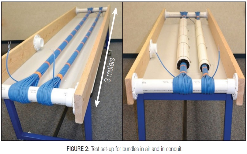
An example of the test setup is shown in Figure 2. A single length of cable was wrapped around two anchored PVC pipes that were 3m apart. The conductors exposed on each end were soldered together in a way that allows current to flow through each pair of the cable. In both pictures, the bundle on the left contains 61 cables and the bundle on the right contains 37 cables. The picture on the left in Figure 2 shows the testing for temperature rise in open air. The picture on the right shows testing for temperature rise in a closed conduit. For the testing in conduit, the conduit was split down the center and assembled around the bundles so as not to disturb them. This was done so that the same bundles used for testing in air could be used in the conduit testing without introducing other variables that might alter the results. The ends of the conduit were stuffed with insulating material to prevent convection air from entering the conduit. The size of the conduit was selected for a conduit fill ratio at or below 40 percent.
Temperature Rise vs. Category and Number of Cables
As a result of the improved measurement procedures and additional modeling, TSB-184-A provides tables that summarize temperature rise for the different cable categories vs. the number of cables in a bundle. Categories 5e, 6,6A and 8 are included in the table. 26AWG is also included for cord cable. The TSB assumes that the results for 26AWG apply to all balanced twisted-pair cables of that gauge size for all categories of performance. Three separate tables are provided based on the current used to energize all pairs of every cable.
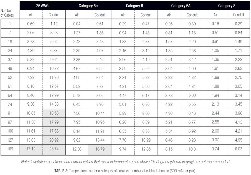
Table 3 shows the temperature rise for category cable versus the number of cables in a bundle in air and conduit when every cable pair is energized with 600mA. There are similar tables showing results when energizing all pairs with 720mA and 1000mA in TSB-184-A. As noted in the table, installation conditions and current values that result in a temperature rise greater than 15¡æ (27¨H), shown in gray, are not recommended.

Using the modeling, a table was created to summarize recommendations for the maximum bundle size for a 15¡æ (27¨H) temperature rise. Table 4 summarizes the maximum bundle size when the ambient temperature is 20¡æ (68¨H). An additional table summarizes the maximum bundle size when the ambient temperature is 45¡æ (113¨H) in TSB-184-A.

Testing showed that separating a larger cable bundle into several smaller cable bundles can help reduce the temperature rise (Figure 3). Comparing the measured temperature rise in the center of a large 91-cable bundle to the worst case maximum temperature rise in the center of three smaller 37-cable bundles, the center temperature of the three smaller bundles was about 25 percent lower even though there were more total cables (111) in the smaller bundles. Separating the smaller cable bundles by an inch reduced the maximum temperature rise by another 30 percent. The smaller bundles have more surface area to dissipate heat and separation allows for more airflow so both can help mitigate temperature rise.
Considerations When Selecting Cable
When selecting cable that may be used for both data and remote powering, there are several things to keep in mind. First, cable construction impacts temperature rise. Larger gauge cable has less dc resistance and heating in a cable is directly related to dc resistance per unit length. As a result, larger copper gauge cables generate less heat and are better at dissipating heat so they are better at limiting heat rise.
Higher temperature can cause additional insertion loss in cables. Cables with a higher temperature rating are better able to mitigate the impact of temperature rise. Plenum cables (100 percent fluorinated ethylene propylene [FEP] insulation) will have a higher temperature rating than riser cables (with partial FEP or polyolefin insulation). Shielded products dissipate heat down the length of the cable and therefore help abate temperature rise.
The design of the cabling system should take into consideration the temperature along the whole cable pathway. Higher temperature may result in insertion loss and could require de-rating the maximum channel length. Also consider the manufacturer¡¯s headroom warranties to estimate performance.
Related Standards Work
Additional work is being done in the TIA Engineering Subcommittee TR-42.3, which is responsible for the pathways and spaces standard ANSI/TIA-569-D. The work will become a second addendum to the standard (ANSI/TIA-569-D-2) when complete.
The addendum provides additional guidelines for pathway systems supporting copper cabling used for remote power delivery. It identifies key considerations when designing pathway systems for new installations and for optimizing the use of existing pathway systems for better thermal performance. This addendum refers to TIA TSB-184-A for guidelines on limiting bundle sizes of different cable categories. The TIA TR-42.7 Subcommittee for copper cabling and components is currently reviewing a suggestion to include 28 AWG cable for cordage. Work is still in the early stages; technically, however, 28 AWG will support remote power. Refer to the manufacturer for guidelines for the support of PoE over 28AWG cords.
Conclusion
The next generation of PoE is coming and it will make it possible to connect significantly more devices because of the higher power. The adverse side to higher power is the generation of additional heat, which can impact the cable¡¯s performance. Temperature rise can cause signal degradation and long-term damage to the cable if the temperature exceeds the cable rating. TSB-184-A recommendations are based on minimizing the temperature rise of cables to 15¡æ (27¨H). The TSB recommends category 6A or higher performance, balanced four-pair cabling as specified in ANSI/TIA-568-C.2. This is because category 6A has the best thermal performance, can be bundled in the largest bundle sizes without exceeding a temperature increase of 15¡æ (27¨H) and supports 10 GBASE-T (10 gigabit Ethernet). The TSB recognizes category 5e or higher for existing installations.
TSB-184-A also recommends leaving cables unbundled in pathways. If bundling is necessary, then the guidelines for maximum bundle sizes provided by the tables in Annex A of the TSB, like that shown in Table 3 for 600mA per pair, should be followed. As a general rule, TSB-184-A recommends limiting the bundle size to 24 cables in typical pathway conditions like conduit or tray without insulation. This takes into consideration installation practices, possible high ambient temperature, the use of 26AWG cords, and higher current (1A per pair; 500mA per conductor) with all four pairs energized. The administration system, as defined in ANSI/TIA-606-B, may be used to distribute channels supplying power in different bundles to help mitigate temperature rise.
Some argue that in 2017 remote power delivery is primarily accomplished over two pairs and IEEE 802.3bt standard for Type 3 and 4 PoE will not be published until 2018, whereas the modeling done in the TSB was based on all pairs being energized in all cables. Standards will always be based on the worst case because they are providing guidance that can be used no matter what manufacturer¡¯s product is used for an extended amount of time. Cable plant life can be anything from three to five years for some or, more commonly, 10 to 15 years or more for others.
It is important to remember the following key concepts related to supporting the delivery of remote power to find the best solution:
All categories can support remote powering. Higher category cable is larger gauge resulting in lower dc resistance and therefore less heat generated.
l Limit bundle size of smaller gauge cable where heat may be a problem. Separation of bundles can also help reduce temperature rise significantly.
When designing the cabling system, consider the bundle size recommendations for planning the location and grouping of horizontal cables, consolidation points and work area outlets. If larger bundles are needed because of the number of cables in a particular pathway, use smaller adjacent bundles instead.
Make certain that the ambient temperature plus cable temperature rise (maximum increase of 15¡æ (27¨H) does not exceed the temperature rating of the cable. This must be considered for the whole path of the cable. Consider cables with higher temperature ratings if needed.
Channels can be de-rated to compensate for insertion loss.
Cables can be unbundled or put into smaller bundles, or bundles can be separated to mitigate temperature rise.
All cable sizes and TIA performance categories can support PoE; however, they may require smaller bundles or no bundling, or even derating the channel length. Consider the manufacturer¡¯s headroom warranty when evaluating performance. Some manufacturers have developed cables for accommodating various specific needs (e.g., low data rates supporting higher power delivery vs. high data rates supporting high power delivery). Keeping TSB-184-A guidelines in mind, along with identifying the fastest data application and highest level of remote power expected to be delivered over the life of the cable, will help in the selection, design and installation of the right cabling system solution for the life of the cable plant.
Recommend
-

-

QQ Zone
-

Sina Weibo
-

Renren.com
-

Douban

